(a) schematics of the pipe flow setup, with a representation of the Solved flow entrance to pipe is given in figure (a). Schematic of rotating pipe flow facility.
Sale > single pipe central heating system > in stock
Boiler system: combi boiler system diagram Flow return diynot hi Piping boilers hydraulic separator plumbing closely needed circulators siegenthaler grouped piped
Pipe two heating return reverse layout system central diagram piping radiator hydronic systems pumped typical do
Pipe velocity flow fluid steel schedule metric units pdf diagram fileFlowchart for the single-use (top), return (middle) and refill (bottom Piping plumbing identicalTroubleshooting headaches plumbing.
Schematic diagram of engine cooling systemWhen and how to use reverse return piping Boiler combi boilers navienWater flow in a two pipe direct return system diagram.

Radiator piping diagram
Microbore heating system designPipe outlets pipes pipeflow gif A schematic diagram of the pipe flow facility. (online version inFlow returns return warehouse slideshare.
Water flow in a two pipe reverse return system diagramPipeflow1.gif Solved for each pipe layout, your design should include theSchematic diagram of pipe flow facility..

Internachi inspection graphics library: hvac » heating » two-pipe
Flow and return identification. : r/plumbingPipe marker An installed return flow grid assembly.Example: default flow direction for pipeline with loop series.
Flow and returnSide perspective Sale > single pipe central heating system > in stockReturns flow.

Pipe return boiler hydronic two water direct loop loops piping systems hvac highperformancehvac
Reroutes, which reverse the flow direction in a pipe.Pipe system return two direct heating hvac 2d Schematic diagram of pipe flow facility.Water flow charts based on pipe size (gpm/gph) ie, how much, 58% off.
Microbore heating system designTroubleshooting headaches – the return pipe that was a supply When and how to use reverse return pipingDo control valves have a preferred flow direction & piping layout?.

Pipe flow
Boiler water loops .
.


An installed return flow grid assembly. | Download Scientific Diagram

PPT - Final Design Project PowerPoint Presentation, free download - ID
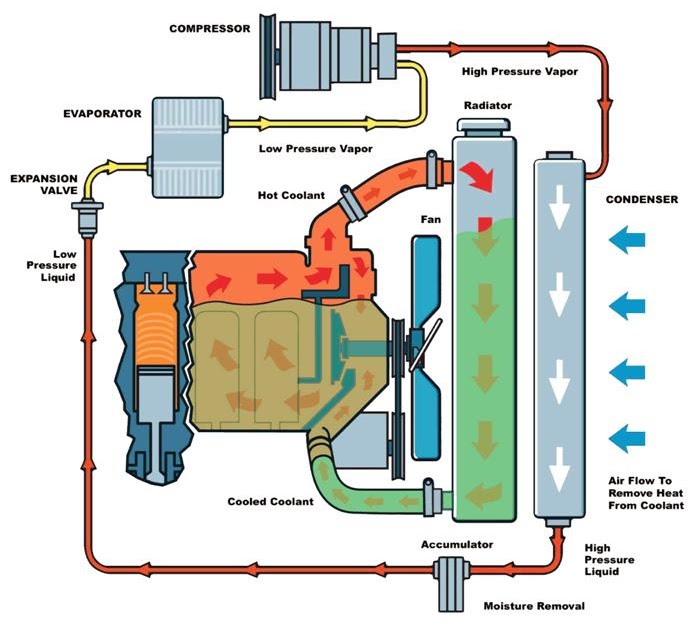
Schematic Diagram Of Engine Cooling System

InterNACHI Inspection Graphics Library: HVAC » Heating » two-pipe

Solved Flow entrance to pipe is given in figure (a). | Chegg.com

Boiler Water Loops | HVAC Hydronic Piping Systems

Sale > single pipe central heating system > in stock